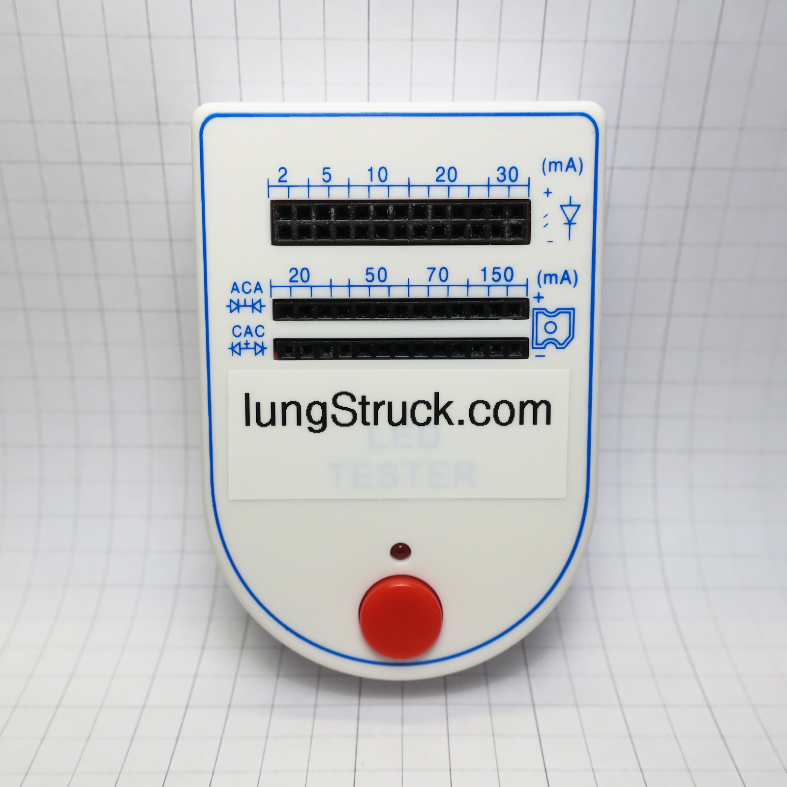
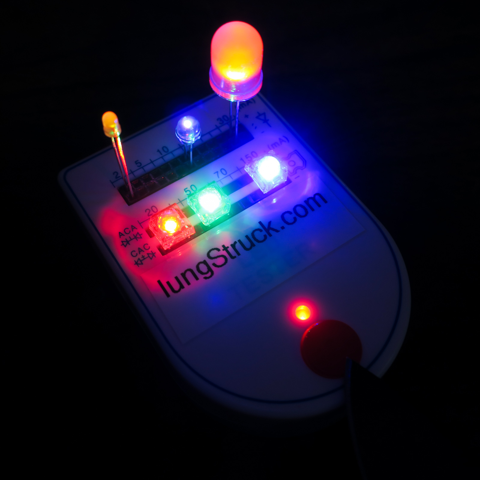
This little LED test box couldn’t be simpler – pop an LED into the tester, push the button, and see it light up. The top header accommodates standard LEDs with two leads, and the bottom headers accommodate 4-pin “piranha” LEDs. I use it frequently when assembling LED lighting projects or to quickly test a new batch of LEDs. It’s a great value for the approximately $2.00 USD that I paid for it. With that said it has some issues, and there are a few things to be aware of when using these testers.
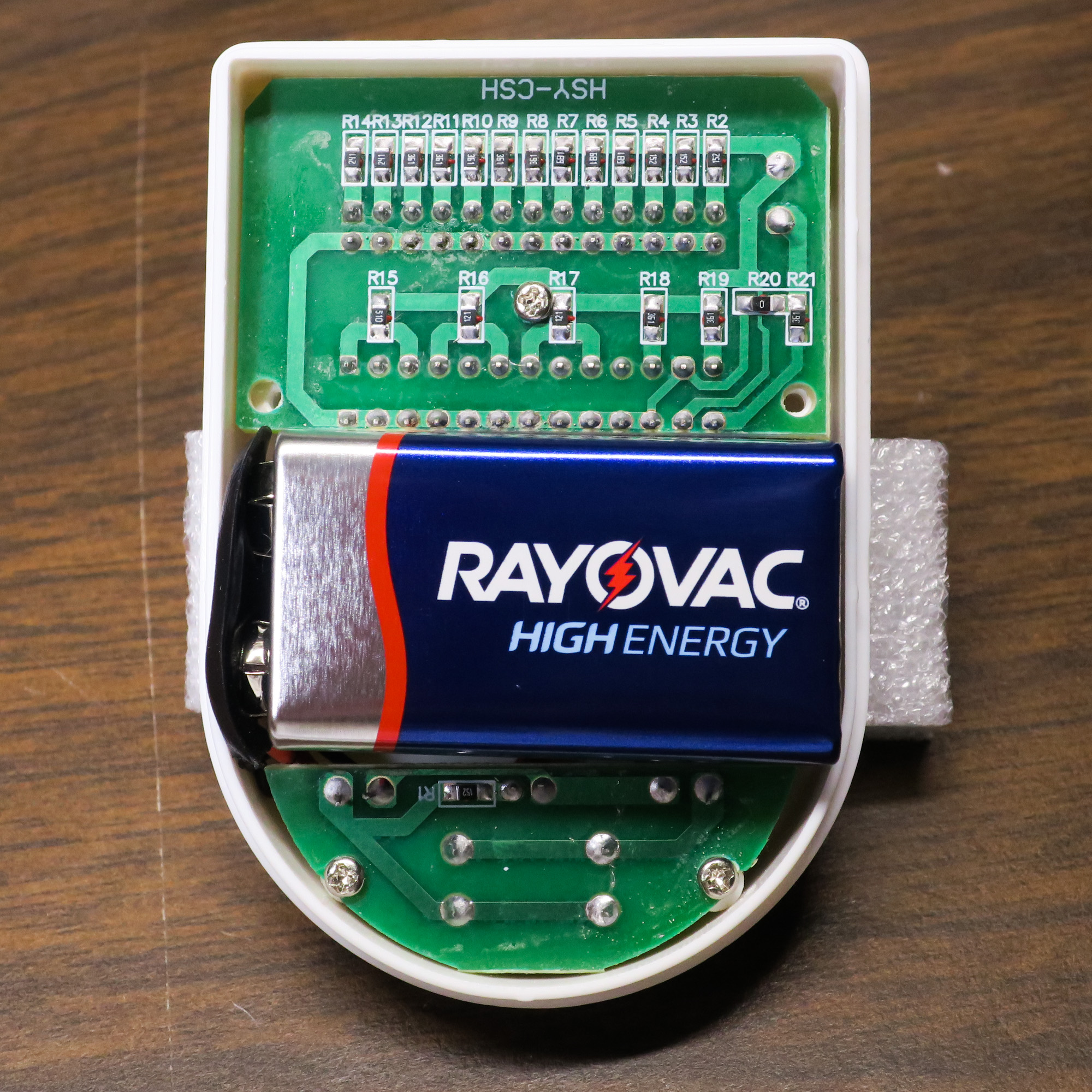
You can’t expect much for $2, but the quality is fine for the price. The biggest issue I have is the headers; they don’t always make good contact with the leads on the LEDs, especially the bottom rows for piranha LEDs. So sometimes I have to fiddle around with the LEDs to get solid contact. The other minor issue is the battery compartment; it’s fairly tight and I’ve had some trouble figuring out how to best orient the battery so it will fit with the case closed. With a little trial and error though, it’s possible.
These are minor quibbles, and acceptable given the price. But there are some more concerning issues with the circuit itself, which I’ll cover in the next couple sections.
Electrically, the tester is very simple – it uses resistors to achieve the current values listed on the case. This means that a specific forward voltage must be assumed when the resistors are selected. Based on the values chosen, it seems that 2v was used, which makes the current ranges accurate enough for LEDs with a forward voltage between 1.5v and 2.5v. This includes most red, orange and yellow LEDs. For LEDs with a forward voltage of 3v+ or more (white, purple, etc.), the current may be noticeably less than indicated.
This in itself is fine, but the problem is that for several positions on the tester, the marked current is entirely wrong, because the wrong resistor is installed. In fact, some positions which are marked for the same current do not even have the same resistor values! Take the first six positions at the top for example – there are two positions each for 2mA, 5mA and 10mA. However, the first three positions have a 1.5kΩ resistor, which will result in approximately 5mA of current with a 2v LED. The next three positions then have a 680Ω resistor, which results in approximately 10mA. So out of the first six positions, only three are correct, and it’s not even possible to test at 2mA!
I drew a schematic showing which resistors are actually installed (click on it for a higher-resolution copy):
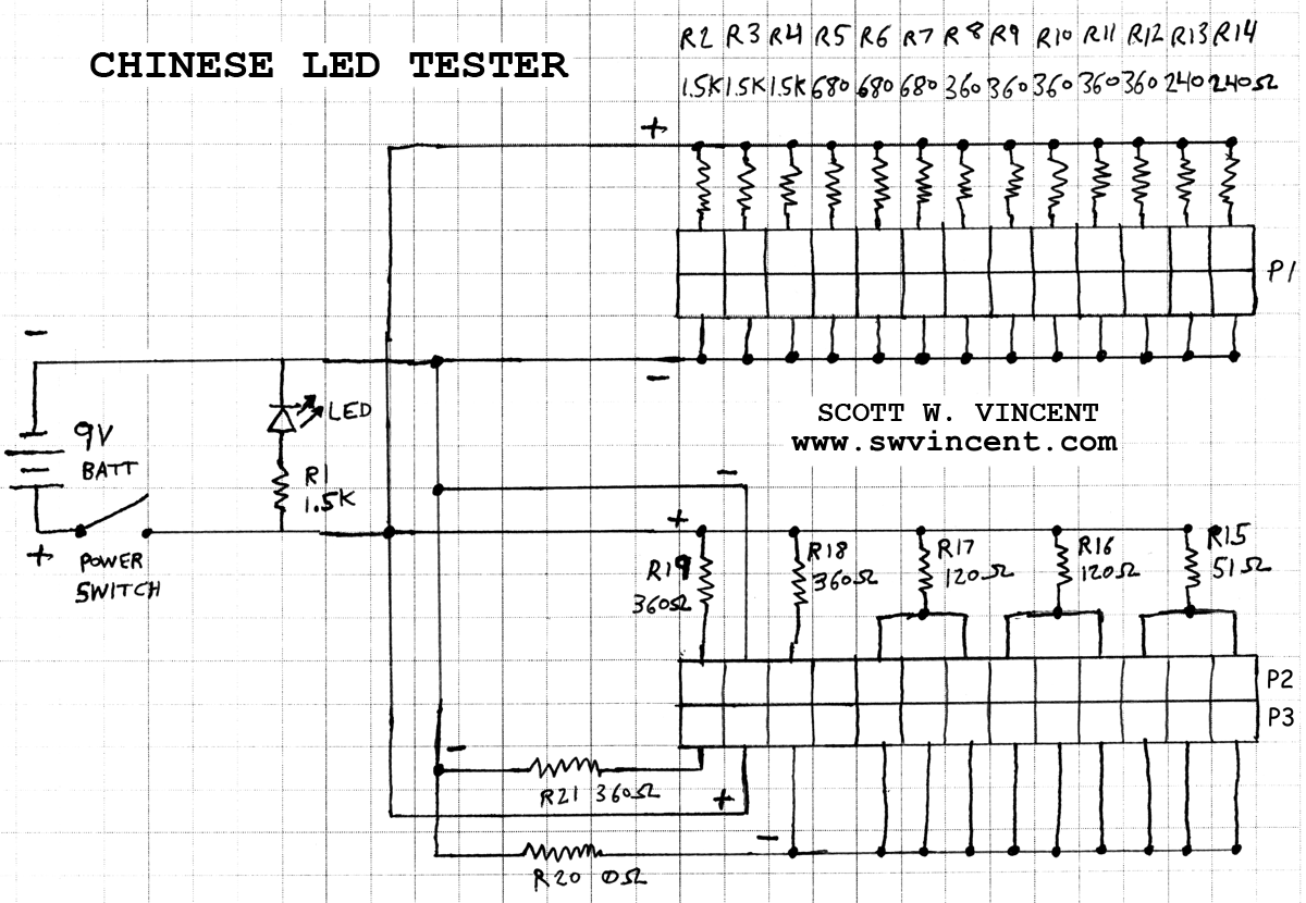
Based on the schematic, here’s a chart showing what to actually expect when using the tester:
| Chinese LED Tester resistors and current | |||||||
| LED Type | Positions | Marked current (mA) | Resistance | Approximate current in mA w/ forward voltage of: | |||
| 1.5 | 2.0 | 2.5 | 3.0 | ||||
| Standard | 1,2,3 | 2mA/5mA | 1500 | 5 | 5 | 4 | 4 |
| Standard | 4,5,6 | 5mA/10mA | 680 | 11 | 10 | 10 | 9 |
| Standard | 7,8,9,10,11 | 10mA/20mA | 360 | 21 | 19 | 18 | 17 |
| Standard | 12,13 | 30mA | 240 | 31 | 29 | 27 | 25 |
| Piranha | 1&3 | 20mA | 180 | 42 | 39 | 36 | 33 |
| Piranha | 5&7, 8&10 | 50mA/70mA | 120 | 63 | 58 | 54 | 50 |
| Piranha | 11&13 | 150mA | 51 | 147 | 137 | 127 | 118 |
Note: The 20mA position for Piranha LEDs has two 360Ω resistors in parallel, resulting in 180Ω of resistance. More on that later.
As the chart shows, there is a bit of a disconnect between what the case says and what is actually happening in the circuit for several of the test positions. This is important, as the tester can potentially supply more current to an LED than indicated. So it’s good to be aware of this and know what current can actually be expected in each test position. The problems do not end here however…
If you look at the schematic, the 20mA position for piranha LEDs is wired much differently than the other piranha LED test positions. Based on the markings on the case, it seems these pins are meant to double as a test position for three-pin bicolor LEDs utilizing either a common anode or common cathode on the center pin. Unfortunately, this has not be designed correctly, and the result is that this test area doesn’t work as expected, and can even damage some LEDs.
First, let’s look at the common cathode test position, which uses the first three pins of header P2. Pins 1 and 3 are both connected to 9v+ through a 360Ω resistor each, and pin 2 is connected to 0v. This is correct, and will result is both sides of the LED receiving 20mA, assuming a forward voltage of 2v.
Now, let’s look at the common anode test position, which uses the first three pins of header P3. Pin 1 is connected to 0v through a 360Ω resistor, which is correct. However Pin 3 is not; it’s tied to 0v without a resistor. And since pin 2 is connected directly to 9v+, this means that if you connect a three-pin common anode LED here, one side will receive 9v+ with no resistance, and burn out as a result. I demonstrate this in the following video:
In addition to this issue, the other problem is that for piranha LED testing, this position is not 20ma. The two 360Ω resistors used for the common cathode test work in parallel when connected to a 4-pin piranha LED, which works out to 180Ω of resistance on the anode. The 360Ω resistor on the cathode is ignored since there’s a direct connection to 0v on the other pin, so the resistance ends up being 180Ω, which results in a current of approximately 40mA!
This is just poor engineering, as the circuit board is not designed to allow this position to work correctly for all three tests. For me, the most important test is to be able to run piranha LEDs at 20ma, so I removed resistor R19 and jumpered positions 1 & 3 together so they share a single 360Ω resistor, then I removed resistor R21 and jumpered it to 0v since it wasn’t going to be used anyways. Here’s the modified circuit board:
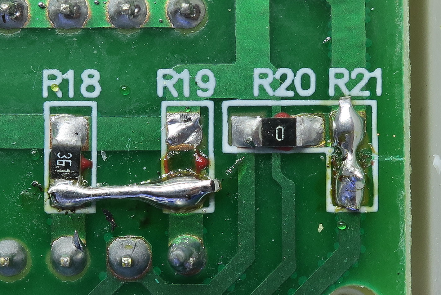
Now I can run piranha LEDs at 20mA, the bicolor LED tests are gone, and there’s no risk of damaging an LED by accidentally connecting it directly between 0v and 9v.
The LED Tester has some shortcomings that could potentially lead to damaged LEDs, but overall it’s quite usable and does the intended job fairly well. And the problems it has are not out of the ordinary for such an inexpensive product purchased directly from China. With modification, some of the problems can be fixed – I’ve considered replacing the headers and possibly replacing some of the resistors so the current values are correct, but given the cost and trouble of doing so, I’ll likely continue using the tester “as-is”. For $2, I can’t complain.
Back to Electronics | Back to Main Menu
Originally posted February 12, 2017 on my old site; posted here April 6, 2018 with minor revisions.