I love headphones - it’s the only way I can listen to music much of the time. At work I listen on Grado SR-80’s, which allow external sound to come through so I can still hear my phone ring and be aware of what’s happening around me. At home, I wear closed phones like my Ultrasone HFI-580’s so I don’t have to hear what’s happening around me, allowing me to enjoy my music and movies in peace. With all of this headphone listening, it was inevitable that I would eventually take an interest in headphone amplifiers, and I did. Recently, I built the Objective2 headphone amplifier (actually, I built two – one for home and one for work) and in this article I’ll cover what led me to the Objective2 amp and my experience building it.
My criteria for a headphone amp
I’ve purchased and built a few headphone amps, but until recently I hadn’t seen or heard any I really liked. Part of is it probably my choice in headphones. The SR-80 and HFI-580 are both very efficient headphones with a 32-ohm impedance, so they don’t need an amplifier; any device with a headphone jack should be able to drive them. But there are other reasons for using an amplifier besides voltage gain. For me, the primary reasons are:
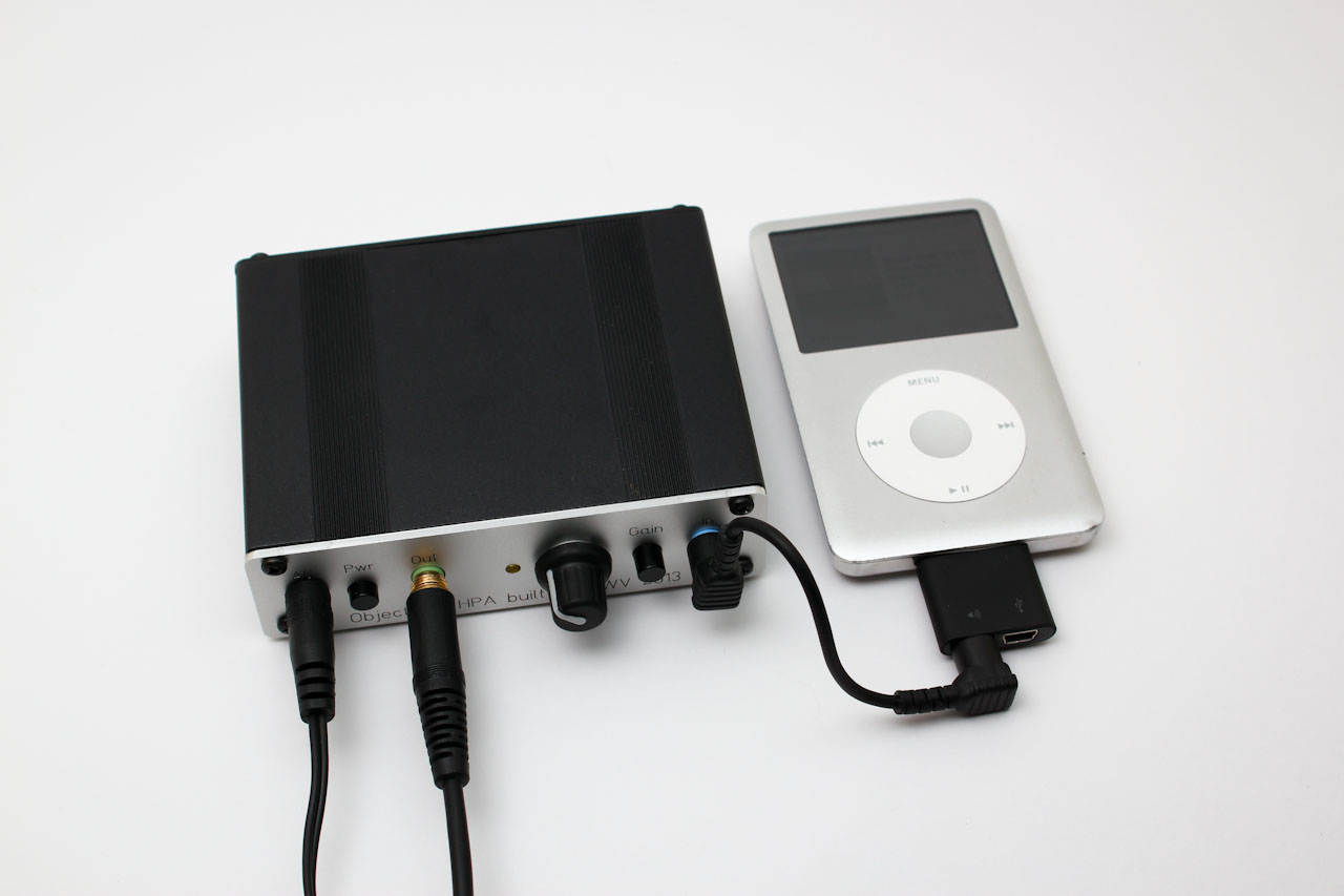
- Cleaner Output – My iPod Classic is a good example of this. The built-in amplifier picks up noise from the hard drive, resulting in an occasional clicking sound. The line output is not affected by this, so running it through an external amp removed the noise.
- Because no built-in amp is available – My TV doesn’t have a headphone output, only line-level outputs. As a result, an external headphone amp is required.
- Current – Low-impedance headphones need more current, and not all devices provide enough, which affects sound quality.
- Output Impedance – Devices with too high of an output impedance can also affect sound quality. This is especially true for low impedance headphones.
So then, which amp to use? The cMoy won’t work, as it doesn’t provide enough current for low-impedance headphones like mine. The Grado RA-1 is an obvious choice, but it’s too expensive, especially when it’s little more than a cMoy itself with a higher-current OpAmp. I could build an RA-1 clone, and actually, I did; but it didn’t come out too well. I could tackle it again, but I really wanted to build an amp that I know would work. Finally, I could buy one, but I really like the idea of building one. So I sought out a well-designed, properly-engineered amp that I could build, and I found it in the Objective2 headphone amplifier.
The Objective2 Headphone Amp
The Objective2 headphone amplifier was designed by a person known online as NwAvGuy who has remained quiet for several years now. There's a bit of controversy surrounding this person and their work, but none of that means much to me. I chose to build this amp because I saw several things I liked in the design and supporting website, such as:
- An objective approach – the O2 design is based on electronics engineering know-how, not opinions or superstition.
- A neutral sound – I’ve seen many people call the O2 neutral, or even “analytical”. Good. I want my amp to do its job without adding its own flavor to the sound. My headphones do that already.
- Low cost – It’s not as cheap as a cMoy, but it’s very affordable, especially compared to many of the exotic audiophile amps available.
- Compatible with low-impedance headphones – The O2 can provide plenty of current, and has an output impedance of just .5 ohms. With properly selected gain, it’s perfect with my Grados and Ultrasones.
- Switchable gain – A very useful feature to have, which isn’t found on all designs.
- AC powered – I don’t want to have to keep charging batteries and swapping them like I’ve done in the past with my cMoy. The O2 can run off AC or battery power, and it has built-in battery charging.
- Well documented – NwAvGuy’s website contains tons of information on the design of this amp, how it works, and how to build one. I’ve spent several hours on there learning about it before and after building one.
Acquiring the parts
If you’re interested in building one, and want to make it easy on yourself, there are kits available. I can’t vouch for any of them as I didn’t use a kit, but JDS Labs has one, and my experience with them has been very positive so I’d expect it’s a good kit. Actually, if you want to make things really easy on yourself, you can just buy an Objective2 amp fully assembled from JDS Labs and others. But I wanted to build my own, and I wanted to customize a few things, so I purchased all the components myself, using NwAvGuy’s bill of materials as my guide. It seemed like a monumental task, and I was a bit nervous about getting it right, but I took my time, and double checked everything, and I got it 99% right. I did miss a single resistor (very frustrating!) but that made for a good excuse to place another order with Mouser and build something else. :-)
I got the lion’s share of parts from Mouser. The case and a couple things Mouser didn’t have came from Allied Electronics, and the PCB came from JDS Labs. I had a custom front panel made by Front Panel Express, and I got my 250mah 9v batteries from an Ebay seller. Overall, I built mine “to spec”, but I made a few changes, all of which are based on NwAvGuy’s own notes. They are:
- Lower gain resistors – On my initial build, I went with the default resistors, giving me a low gain of 2.5x (8 db) and high gain of 6.5x (16 db). That’s a bit much for my 32 ohm headphones, though it is useable. At 2.5x gain, I can’t turn the volume knob very much, and 6.5x is completely unusable. I later changed it to a low gain of 1x (no gain) and high gain of 2x (6 db), based on the recommendations on NwAvGuy’s All About Gain page. These are great settings for the Grados and Ultrasones. It might seem pointless to have no gain on an amp, but as I pointed out in the criteria section, there are lots of other reasons for using a headphone amp than gain.
- Battery charging resistors – On my first build, I went with 270 ohms, because I rarely expect to use it on battery power since I only use it at my desk at work (actually, I ended up removing the batteries.) For my second O2 amp, I went with 240 ohms, as I felt 270 might be too extreme, especially with the 250mah batteries I chose for the second amp. It still charges very slowly, but that’s okay as it’s plugged in for days at a time.
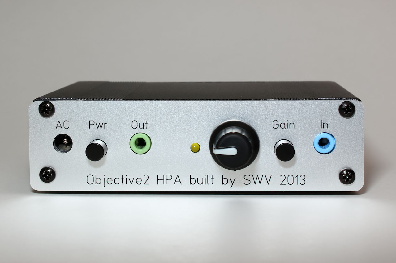
- Yellow LED – The only reason for this is that nobody had the recommended red LED in stock. Of all of the parts I needed to buy, it was only the LED that I could not find anywhere. If you’ve read up on the O2 circuit then you know the LED is a critical part of the power management circuit, so any old LED won’t do. NwAvGuy listed an alternative yellow LED, which Mouser had in stock so I bought it. I may switch it to a red LED if I ever find it in stock, but then again, who says power indicator LED must always be red or blue? I may just get used to it.
- Input/Output jack colors – The BOM calls for two blue audio jacks, but I went with the more standard blue for input, and green for output.
- Custom front panel – I was very tempted to just buy the JDS Labs panel for $9 since it’s a good deal, but I didn’t want the “Distributed by JDS Labs” text on my amp. Nothing against them, but I’m building the amp, not them. They also use symbols on the panel, and I prefer seeing actual words. So I had mine custom made to include my initials and the year. This was done by Front Panel Express, using the file developed by NwAvGuy. It wasn’t cheap, but I take a lot of pride assembling this project on my own, and FPE did a fantastic job on the panels. If you order from them, make sure to check their Facebook page; they sometimes post pretty substantial discount codes on there.
- Power supply – I went with the Triad Magnetics WAU16-400. The WAU12-200 is about half the price, and it probably would have been good enough, but for an extra $5 I have a supply that I know will always work.
Assembling the amp
The circuit board
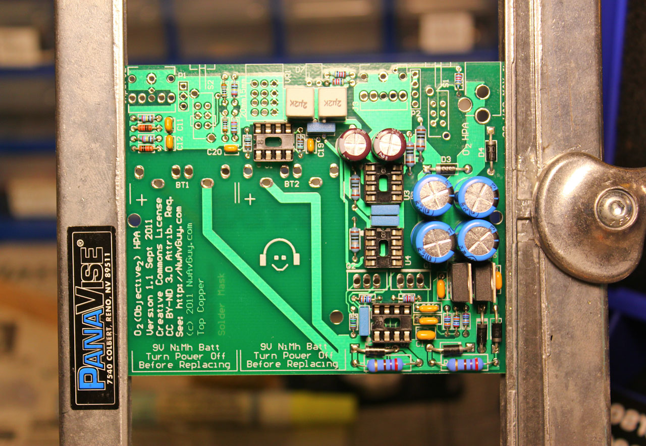
There are no step-by-step instructions for building the O2 circuit board, but following the general rule of starting with low-profile parts first (resistors, small caps) and working your way up will make it much easier. I’ve built a few kits in the past, so I felt confident I could handle this. I read the instructions on the O2 Details page several times and printed it out so I could refer back to it as I assembled the board. There are several very important tips on there that may not be obvious, such as a couple areas where a lead or switch leg must be trimmed to avoid a short circuit. I also referred to a post on the diyaudio forums by member 6L6 which covers his O2 build and includes lots of photos. I followed his tip of leaving some room between the battery charging resistor and the PCB as these resistors can get pretty hot.
I used the recommended MG Chemicals RA lead solder, with the only difference being that I used 63/37 instead of 60/40 as I’m used to working with eutectic lead solder. MG Chemicals indicates on their site that the residue from their RA flux is non-corrosive and non-conductive and therefore does not have to be cleaned, which makes sense as NwAvGuy points out that if you use it you won’t have to clean the board. I opted not to, and there were no problems.
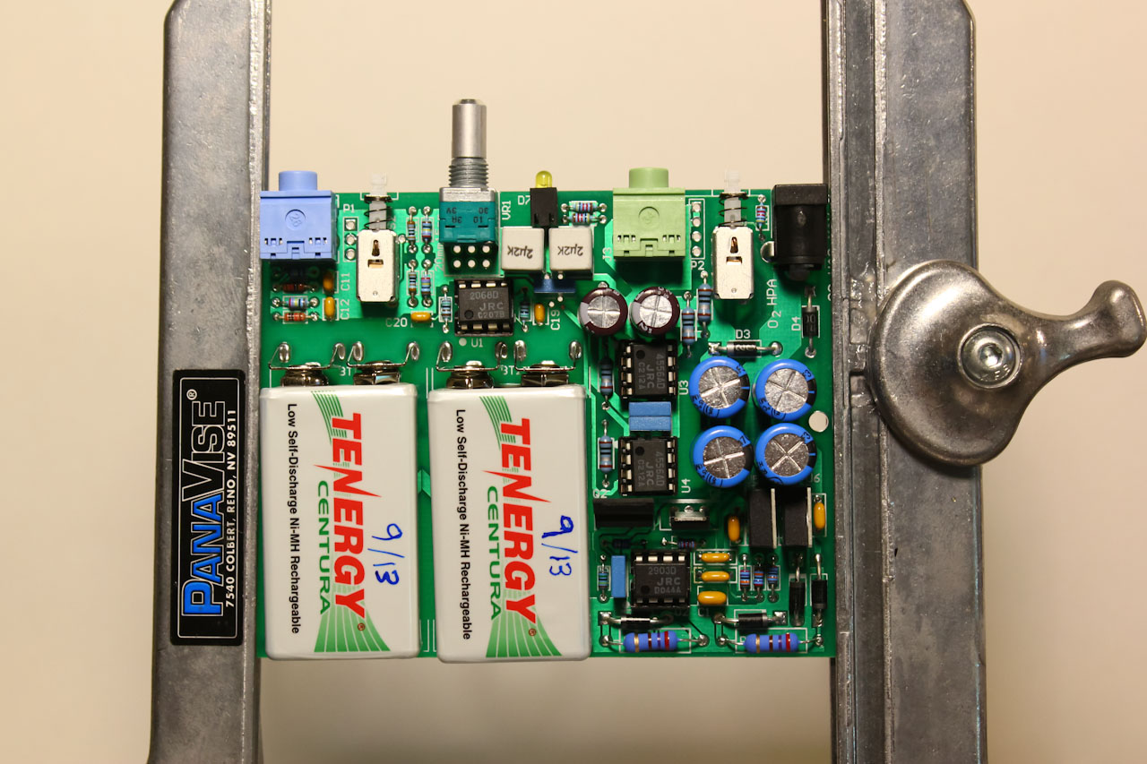
The only part that I had difficulty with was the battery terminals. I got one crooked on my first build, which resulted in tight fit in the enclosure as the battery wasn’t sitting quite where it should. For the second build I was more careful and it came out okay. Make sure you pay special attention to this. I suggest soldering the terminals at a single point, installing batteries, and checking to see if it slides into the enclosure okay. Then once you’re sure it’s lined up okay, finish soldering the terminals in place.
Testing the board and casing it up
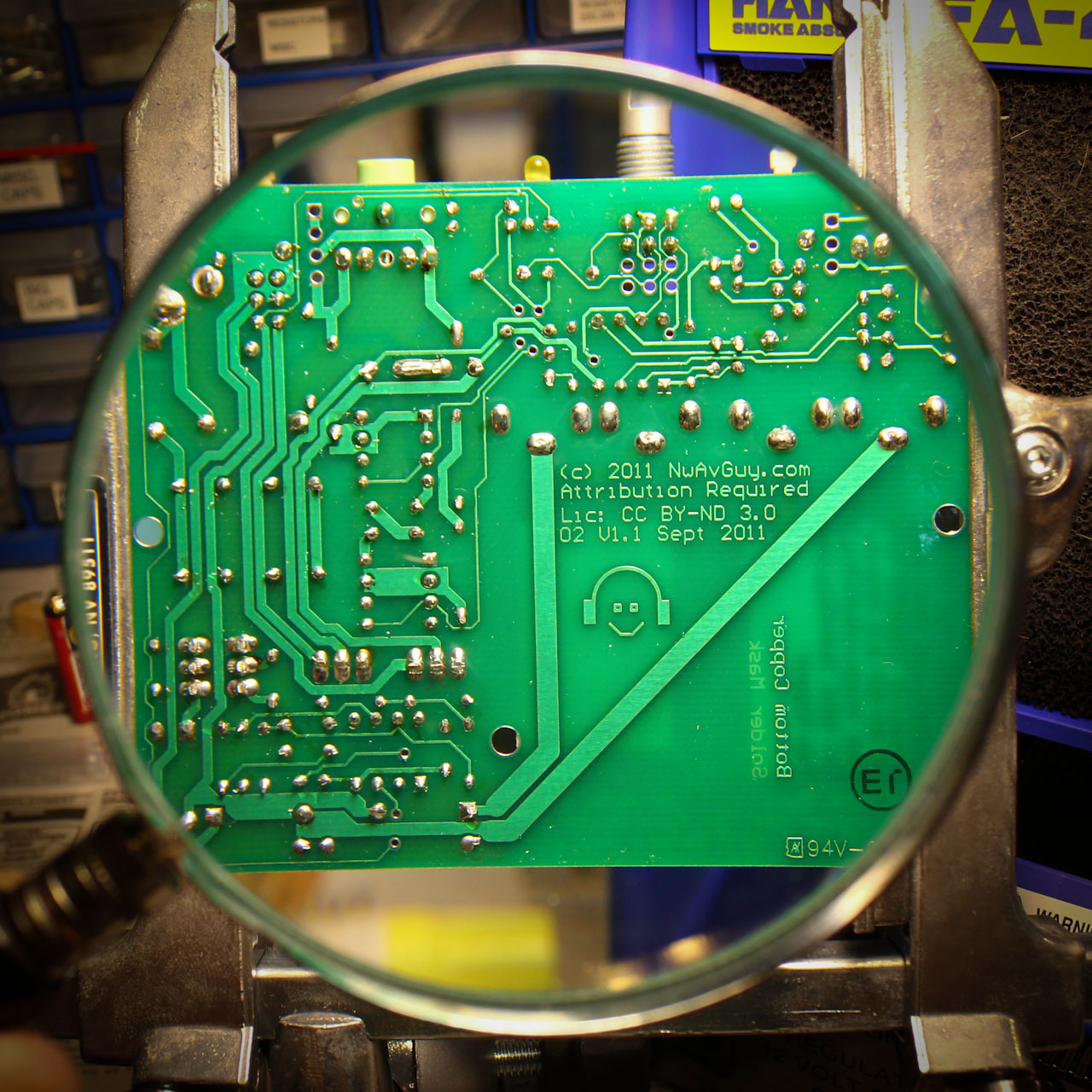
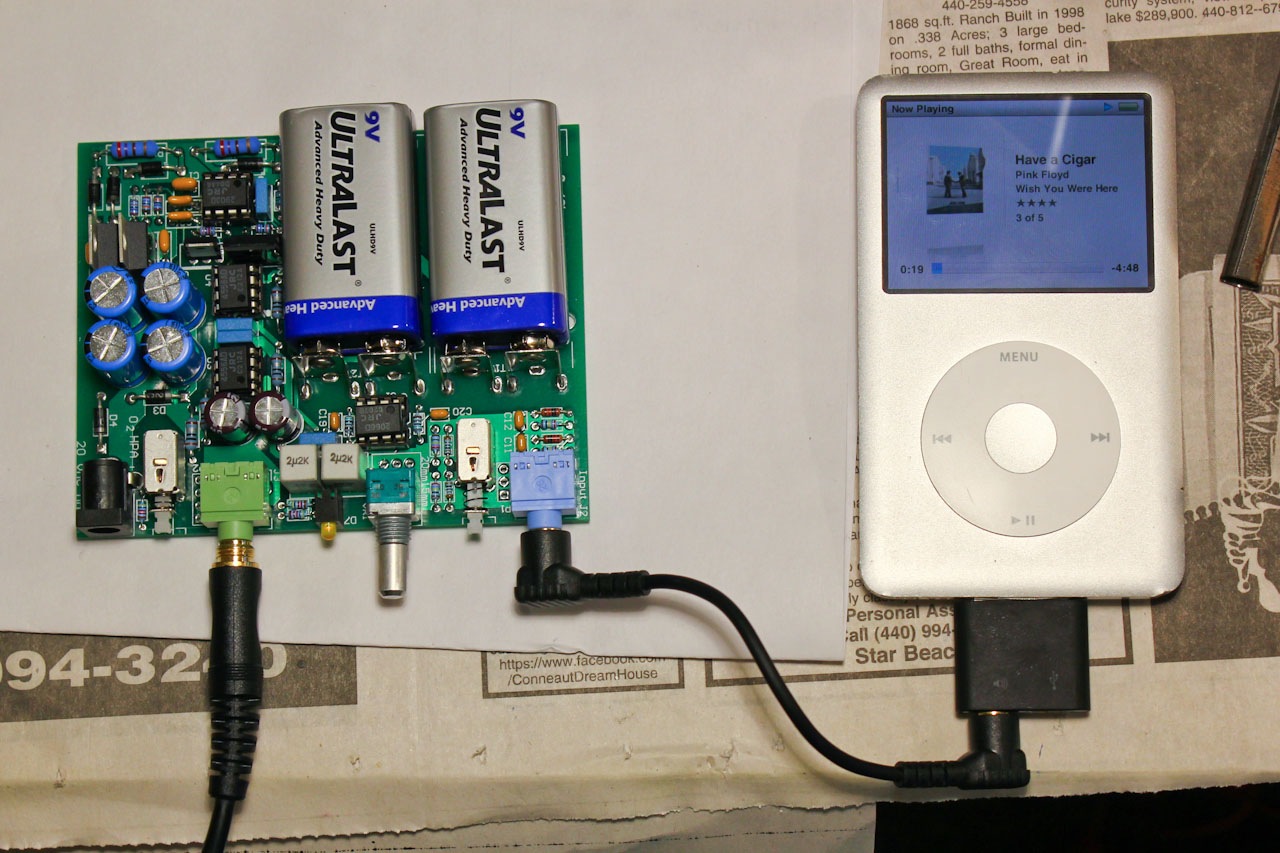
I carefully looked the board over twice on each side with a magnifying glass, ensuring that there were no cold solder joints or solder bridges that could cause problems. I then followed all of NwAvGuy’s testing instructions on the details page. Both of my builds passed with flying colors, with all numbers being well within tolerance of the numbers he suggests. The next test then was to hook up an iPod and some headphones, and try it out. After doing that for each amp, I soldered on the enclosure grounding wire, and slid the completed board into the case (which I had already “pre-drilled” to avoid aluminum shavings getting on the board.) I looked it over carefully to ensure none of the leads were touching the enclosure.
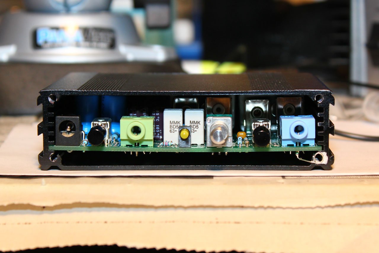
The finished amplifier
I’m quite happy with the finished amplifiers. They sound good, look good, and work well for their intended use. Bass response is especially improved, it has much more punch with the O2 amps than without. I don’t get the feeling that the headphones are being strained as I do with some other amps I’ve used. With the gain resistors I selected, they work great with both of my headphones. I haven’t had any sources that overload the inputs, and I doubt I will at the gain levels I chose. The built-in rechargeable battery is a big plus on my O2 that I use at home. The O2 is too bulky for me to consider using it as a truly portable amp, but it’s nice being able to unplug it from my desk and take it over to the couch while watching TV for a couple hours. I think I finally found the amp I’ve been looking for in the O2, and I expect my two O2 amps will serve me well along with my Grados and Ultrasones for years to come.
Update: As of 5/7/2018, I'm still using my Objective2 amps and love them just as much as when I first built them!
More Audio Projects | Back to Main Menu
Originally posted November 10, 2013 on my old site; posted here May
8, 2018 with a few revisions.